Studio Operation
Describes all of the necessary knowledge to be a pro in the station.
- Control Board
- Playing CDs
- Playing Vinyl
- Original Clearance Video
- Current Clearance Videos
- Phone Clearance Video
Control Board
Getting to know the board
The Board in the station is a Wheatstone A-300. The full manual can be found here.
The Board is split into vertical Modules. These each operate independently, and what follows is an overview of these modules.
Module Type 1: Microphone Input
This module takes a standard microphone input and includes a preamp. The fader in the center controls the final output volume of the microphone.
 The gain hole is a preset value, DO NOT STICK ANYTHING IN HERE
The A/B switch allows you to select between two different inputs for the same channel, however only A is used for all three mics in the studio
The PGM switch should always be depressed. This sends audio from this module to the main output.
The AUD (audition) switch should also always be depressed. This sends audio to the headphone monitoring system
The TEL switch should not be depressed. This sends this module's audio to the caller on the landline module
The pan knob controls the pan of this audio source as it is sent to all selected outputs. For all reasonable applications, the should be centered.
The main fader controls the relative loudness of the microphone as it is sent to the main output. The markings are in decibels. Note: the microphone preamps are failing, so the faders for mics must be turned up between 0 and 5 decibels.
The ON switch turns the audio output of the module on.
The OFF switch turns the audio output of the module off.
Module Type 2: Stereo Line Input
This module takes a stereo (right and left channel) input and produces a balanced output.

There are two gain holes. They are preset values, DO NOT STICK ANYTHING IN HERE
The A/B switch allows you to select between two different inputs for the same channel, however only A is used for all three mics in the studio
The PGM switch should always be depressed. This sends audio from this module to the main output.
The AUD (audition) switch should also always be depressed. This sends audio to the headphone monitoring system
The TEL switch should not be depressed. This sends this module's audio to the caller on the landline module
The main fader controls the relative loudness of the microphone as it is sent to the main output. The markings are in decibels.
The ON switch turns the audio output of the module on.
The OFF switch turns the audio output of the module off.
Module Type 3: Phone Input
This module takes two POTS (plain old telephone system) lines and allows them to be routed to the outputs.
Note: These telephone lines are currently disconnected, but this documentation is included if these become functional again one day

There are two gain holes. They are preset values, DO NOT STICK ANYTHING IN HERE
The PGM assign button puts the caller on with the other modules, this is called a "talk-in"
The record ready button is for a tape recorder to record the callers for playback later
The main faders control the relative loudness of the callers as they are sent to the main output. The markings are in decibels.
The ON switch turns the audio output of the module on.
The OFF switch turns the audio output of the module off.
Module Type 4: Control Room Selection
This module includes various selectors for the studio monitor system.

- EXT1 is unassigned, but may be a studio delay feed
- EXT2 is a re-feed of the cue bus for listening from the studio monitors
- PGM is the DEFAULT and should almost always be used. This is the master feed going to the transmissions cabinet
- AUD is the audition bus and the same feed as the headphone amplifier
- Telephone is not currently connected, but would be the POTS line
- MONO is a monoaural feed (no panning) but the same as PGM otherwise
- MXM is a mixed master that is a combination of the cue and PGM feeds. It should not be used
The cue knob controls the volume of the cue bus to the headphone jack underneath the console.
The headphone knob controls the volume of the headphone jack underneath the console.
The CR knob controls the volume of the studio monitors
Module Type 5: Control Room Selection
This module includes various selectors for the studio monitor system.

The VU Selectors control the switched VU meters (see the faceplate section below). Whatever bus is depressed, that will show on the switched pair of VU meters.
These are all screwdriver controlled rotary potentiometers, and they each are pre set. DO NOT MODIFY THESE OR STICK ANYTHING IN THERE.
Controls the switched vu sensitivity
Controls the PGM vu sensitivity
Controls the final PGM output gain
Controls the final AUD output gain
Controls the TEL, MONO, and MXM bus gains
Auto restarts the timer when a channel is turned on (needs to be fixed)
Starts and stops the timer
Resets the timer
Holds the current time
Playing CDs
Part 1: Understanding the Technology
Before you learn how to play CDs, you need to understand a bit about how CDs work.

The way a CD works is by using a laser to read minuscule bumps in the surface. These bumps represent digital 1s and 0s. The music is encoded in a spiral of data from the inside to the outside of the disk. The most important thing is that you avoid scratching or smudging the discs, or the data will be irreparably damaged.
Part 2: Understanding the Studio Equipment
We have a couple of different CD players in the studio, but we'll just go over the most complicated type of unit, the Marantz PMD 340. This is a professional grade CD player and has superb audio quality.

The most important buttons on the machine are Eject, Exit/Stop, Clear/Cue, and Enter/Play/Pause. These, along with the index +/- buttons, make up all the things you need to ever use on this machine.
The Buttons and Their Functions
- Eject - Pops the CD tray out for loading
- Stop - Immediately stops the playing track and resets to the beginning of the track.
- Cue - Has the selected track ready to play (armed)
- Play/Pause - Stops the currently playing track where it is and resumes it without changing the position.
- Index +/- - Changes the track to be played. Use this to select a specific song on an album.
Part 3: Playing CDs!
- Insert the CD
- Use the index buttons to select the track you want
- Turn on the CD2 or CD3 input on the board depending on which cd player you inserted the disk into.
- Press the Play/Pause button
- Let the music flow!
- Insert the next song in the other CD player and verify it is correct using the cue output on the console.
- Seamlessly (if you have three arms) fade the last track, fade in the next track, and start the CD player at the same time.
Playing Vinyl
Part 1: Understanding the Technology
Before you can play vinyl records, it is important that you understand how the sound you hear is being produced.
From the victrola website:
Vinyl record players are electromagnetic devices that change sound vibrations into electrical signals. When a record spins, it creates sound vibrations that get converted into electrical signals. These signals are fed into electronic amplifiers. Electric amps vibrate and feed the resulting sound into speakers, which amplify it and make it louder. Record players still use the whole needle and groove methodology that a phonograph used, although record players today are much more high tech.
So how do they work exactly? The needle, or stylus of a record player is one of several parts that make up a transducer. A transducer is what changes mechanical energy into electrical energy and changes electrical energy into mechanical energy. The whole system contains a stylus, magnets, coils, cantilever, and a body within a cartridge. The mechanical energy from the sound waves is converted into electrical energy, which is then sent into the amplifier and out to the speakers.
When a vinyl record is made, a needle is used to create grooves in the vinyl that is basically recorded information of the desired sound or music. A needle (or stylus) is also used to read the information contained in the grooves, playing it back so that we can hear the recorded information. On the left side of the groove and on the right side are channels of audio information that makeup stereo sound.
Part 2: Understanding the Studio Equipment
Parts of the turntable
Now that you understand what the needle and grooves are and what they are doing, let's learn the parts of the record player! The record players we use are the Technics SL-1200 family. They are the industry standard for DJing and are famous for their superb sound quality and reliability.
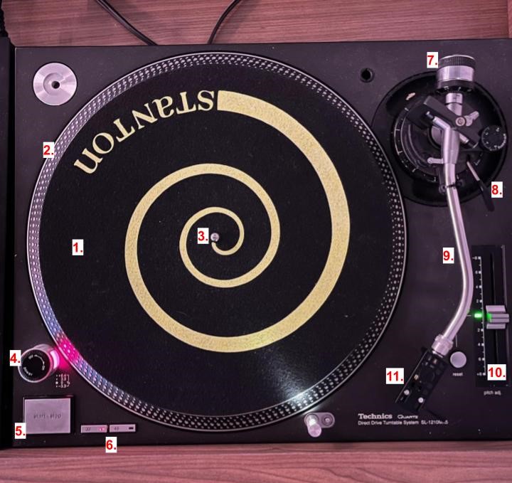
We're only going over the most important components of the record player here, but if you want to learn more, a link to the full manual is at the bottom of this page.
1. This is the turntable slip mat. It rests on the turntable, and prevents damage to the underside of whatever record you are playing.
2. The platter is the main spinning object that is driven by the motor underneath the platter.
3. This is the spindle, and is the center of the player. Be careful when placing a record onto the spindle. If it feels like you need to apply force to get the record on, you're doing it wrong. Make sure you put the record on as vertically as possible
4. This knob is the ON/OFF switch. You will know the player is on if the red light directly below the switch illuminates. You operate the switch by turning it a quarter turn to the right or left.
5. This is the start/stop switch. This turns the motor of the player on or off the moment the button is depressed.
6. These switches select the speed of the player. The options are 33rpm or 45rpm. Large 12" records generally run at 33rpm, and small 7" records generally run at 45rpm. Check the label of the record to verify.
7. This is the counterbalance. The weight the stylus exerts on the record must be very small. This counterweight ensures that this weight is exact all the time. Do not change the counterbalance weight.
8. This bar is called the cue lever. When it is pressed to the back of the record player, it holds the stylus just above the record. When you pull the bar down, it slowly lowers the tonearm (21) and places the stylus on the record.
9. The tonearm connects the stylus and counterweight to the table. Small cables from the stylus run inside the tonearm carrying the audio signal. Be exceptionally careful, and never touch the tonearm itself.
10. Speed control. This fader controls the relative speed of the record. You should generally keep this in the center detent, but if you are trying to match BPM or tone with the other playing record, this can help.
11. This is the headshell which contains the stylus. Only pick the headshell up with your pointer finger under the small hook shaped arm.
The headshell in focus
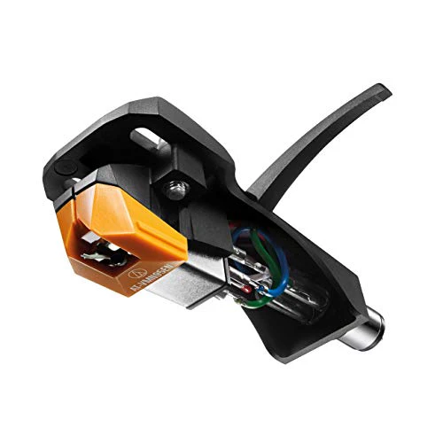
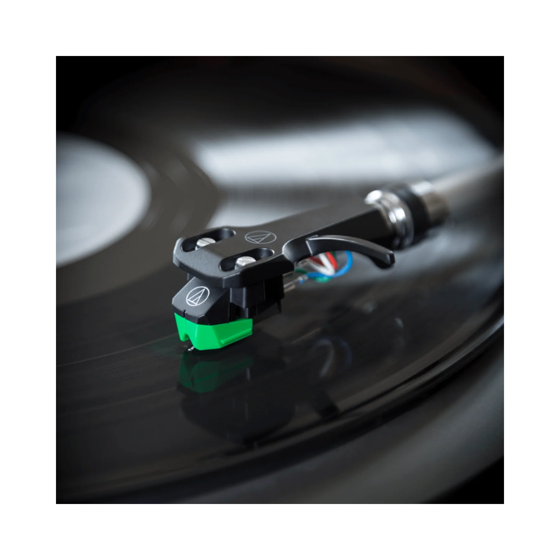
Pay close attention to the stylus, cartridge, and lead wires. These are the most delicate and important elements of the turntable. Do not ever touch anything in the headshell assembly except for the small arm sticking out of the headshell itself.
DJ Mixer
This is the DJ Mixer in between the two turntables. It is nearly symmetrical, so only the distinct features will be described.
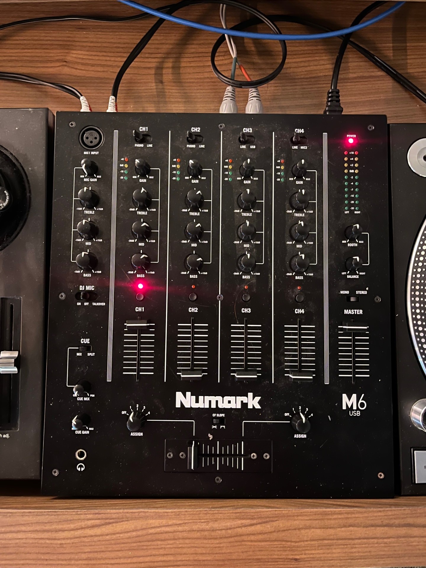
There is a large fader for each player. The left turntable's level is controlled by the left half of controls, and vice versa for the right turntable.
The high, mid, and low knobs control the EQ of the turntable, and have detents at the center.
The gain knobs control the base volume of the player, and should not be changed between tracks. You can change this, but prefer changing the final level at the control board.
The master, mic level, and cue gain knobs all control their respective levels. If you want to learn more about the concept of cueing, see the control board manual.
The cue slider controls which channel is fed into the cue bus.
The center slider at the bottom controls which channel is sent to the output.
The channel for Turntable 1 is Channel 1, and the channel for Turntable 2 is Channel 2.
The curve selectors control the profile of the EQ. The recommended setting is MID
The Phono/Line switch should always be set to PHONO. This is because the Technics turntables do not have built in preamplifiers, so their signals are very quiet. The mixer provides preamplification when the switch is in the phono.
Part 3: Mixing Music!
- Once you have selected the vinyl you want to play, put the first track on the player.
- Lower the cartridge using the cue lever.
- Use the headphone jack on the console and keep the first track off, but cued.
- Turn the player on and find the start of the song.
- When you're ready to play, turn the TT2 input on the board on
- Press the start/stop button, and let the music flow!
- While the first track is playing, place the second on the other turntable and begin finding the start of the next song using the cueing headphones.
- To fade between tracks, smoothly move the slider from one side to another while pressing the start/stop button on the turntable with the track playing next
Original Clearance Video
This is the original clearance video saved for posterity. This does not represent current operating procedures.
Video 1: Studio and FCC regulations
Video 2: Board operation
Current Clearance Videos
Hi! Thanks for your interest in becoming a DJ. The three videos below will show you all you need to know about studio operations at WRBB. It's a lot to take in, so I recommend watching a few times and reviewing your answers on the quiz below
Video 1 – Station and FCC Rules & Procedures
Video 2 – Board Operation
Video 3 – Software Operation
Phone Clearance Video
Hello! Below you will find the phone clearance video as well as a short quiz. Please complete the quiz and watch the video as many times as you need to feel comfortable before using the phone.
Phone Training Video:
Practice Quiz